Application of Simulation Technology to AT-Cut Quartz Crystal Design
Quartz crystals are one of the important components that make up a reference clock for ICs such as microcontrollers. They are widely used in different products, ranging from mobile communication terminal devices such as cellular phones and smartphones to automobiles and home appliances. There has been a strong need for the miniaturization of components, especially for mobile communication terminal devices. Among the challenges in designing such components is accomplishing the miniaturization of products while maintaining the product characteristics. In this article, we present how we efficiently conduct our design work using a simulation technique that employs the finite element method (FEM) .
1. AT-Cut Quartz Crystals and an Oscillator Circuit.
AT-cut quartz crystals are devices made of synthetic crystal and use the piezoelectric properties (thickness-shear vibration) of crystal. Figure 1 shows a typical structure of Murata’s product. Figure 2 shows its equivalent circuit. This device is one of the important components that constitute an electronic oscillator circuit that serves as a reference clock, which is required for the operation of microcontrollers, for example. Figure 3 presents a typical configuration of an oscillator circuit. The oscillator circuit generates clock signals by amplifying electric signals passing through a quartz crystal. The resistance of the quartz crystal varies by frequency as shown in Fig. 4. The resistance of the quartz crystal takes the smallest value at the frequency of principal vibration of the crystal blank. This smallest value of resistance is called the equivalent series resistance (ESR) . The oscillator circuit oscillates near the principal vibrational frequency of the crystal blank, generating clock signals.
What is important in the oscillator circuit is the stability of oscillation. One of the indices of oscillation stability is the oscillation margin , which indicates the ratio of the signal gain (the amplification capability of input signals) of the circuit components other than the quartz crystal to the ESR (a damping factor for signals). In theory, the circuit oscillates when the oscillation margin is greater than 1; however, when the oscillation margin is close to 1, the circuit seldom oscillates or it takes an extremely long time to start oscillating, which may sometimes cause malfunction in devices where the oscillator is installed. Suppressing the ESR can improve the oscillation margin. In general, the lower the frequency, the higher the ESR, and the smaller the product size, the higher the ESR. The 2016- and 1612-size products have been installed in mobile terminal devices, but there is an increasing need for an even smaller product. Hence, design work has been becoming increasingly challenging these days.
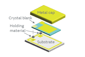
Fig. 1. The Product Structure of Quartz Crystal
Fig. 2. Equivalent Circuit Diagram of a Quartz Crystal
Fig. 3. Oscillator Circuit Diagram
Fig. 4. Frequency Characteristics of the Resistance of a Quartz Crystal
2. Key Factors in Designing the Product Characteristics
The AT-cut quartz crystals have a number of unnecessary vibrations besides the thickness-shear vibration; the latter is used as the principal vibration of the quartz crystals. In designing the quartz crystals, it is necessary to choose appropriate geometric parameters so that these unnecessary vibrations do not affect the product characteristics within the range of operating temperature. Figure 5 shows the relationship between temperature and the ESR, where the characteristics of two cases are compared: the graph (a) represents a case where appropriate geometry is chosen in design, whereas the graph (b) represents a case of inappropriate geometry. When inappropriate geometric parameters are chosen, unnecessary vibrations superpose and increase the ESR. Therefore, it is important to choose appropriate geometric parameters that will not be affected by the unnecessary vibrations in the design phase. However, there are a huge number of combinations for geometric parameters, and engineers have been struggling to find optimum solutions empirically by trial and error in a number of cases. It has been one of the primary causes of trouble in the reduction of the research and development time and the quality improvement of the products.
Fig. 5. ESR Characteristics within the Operating Temperature Range
3. Application of a Simulation Technique (the Finite Element Method, FEM) and New Challenges
An efficient method that we can think of to help us find optimum solutions is to conduct characteristic simulation using the finite element method (FEM). This method, however, has a drawback: The simulation results are poorly consistent with the actual sample characteristics. Recent research has come to elucidate that the source of this inconsistency lies in the fact that not only the geometry but also the holding material connecting the crystal blank and the substrate greatly affects the frequency relationship between the principal vibration (thickness-shear vibration) and the unnecessary vibrations.
Fig. 6. Relationship between Blank Width and ESR
Figure 6 compares the actual sample characteristics and the FEM simulation result when the simulation only modeled the crystal blank without giving any consideration of holding onto the substrate. In the simulation result of a geometry without a holding material, the trend of ESR characteristics did not agree with the actual sample characteristics; hence, appropriate geometric parameters cannot be determined.
Thus, our challenge has been to improve the consistency of simulation results with the actual sample characteristics, and thereby establish a better simulation technique to find optimum solutions efficiently. We have now created a new simulation system that can provide a solution to these challenges. This system has enabled us to improve the consistency of simulation results with the actual sample characteristics.
4. Challenges in the Simulation
Murata’s analytic simulation software of the finite element method called Femtet has been used to improve the consistency of simulation results with the actual sample characteristics. Femtet improved the following four points.
(1) Understanding Absolute Precision and Convergence of Calculation
The finite element method divides the model geometry on a computer into a finite number of parts or sections called mesh for computation. It has been well known that the greater the number of mesh elements we generate by dividing the domain into subdomains as shown in Fig. 7, the better the analytic result converges as shown in Fig. 8.
However, the degree of convergence varies by vibration. The variation in the principal vibration, that is, the thickness-shear vibration, converges in a smaller number of mesh elements, whereas the variation in the unnecessary vibration is unlikely to decrease even in a large number of mesh elements, showing a tendency towards poor convergence, which has been a major cause of poor consistency in simulation results.
Precise simulation of unnecessary vibration modes requires a sufficient number of mesh elements. The required number of mesh elements varies by thickness or size of crystal blank. Understanding the number of mesh elements required for each size and frequency of products has enabled us to conduct the simulation at optimum precision.
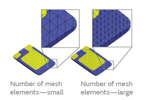
Fig. 7. Mesh Geometry
Fig. 8. Relationship between the Number of Mesh Elements and Frequency
(2) Modeling of Geometry Made Closer to a Real Object
Past modeling used to combine spherical models and others to reproduce the simulated geometry of crystal blanks. However, the geometry of actually manufactured crystal blanks was complex and substantially different from those made in virtual prototyping, which has been one of the primary causes of poor consistency of the past models with the actual sample characteristics.
The use of Femtet’s modeling function has enabled us to reproduce the blank geometry faithfully based on the measured geometric data of real crystal blanks. Femtet allows free modeling of the holding material as well, showing higher reproducibility of actual geometry as shown in Fig. 9.
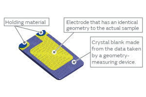
Fig. 9. Femtet Model (Showing the Side with the Holding Material)
(3) Consideration of the Holding Effect
When unnecessary vibrations superpose the principal vibration, the edge of crystal blank vibrates in some cases. In these kind of situations, the model that has no holding material at the blank edge cannot compute the ESR increase because it cannot reflect the damping effect as shown in Fig. 10 (a). On the other hand, the model that has the holding material at the blank edge can compute the ESR variation because it can reflect the damping effect of the holding material as shown Fig. 10 (b).
Femtet facilitates the modeling of the holding material independently of crystal blank, allowing the simulation of the ESR variation similar to the actual samples.
Thus, the modeling of the holding material has enabled us to understand how the ESR varies by the blank width in the same way as the actual samples, as indicated by the blue line in Fig. 11.
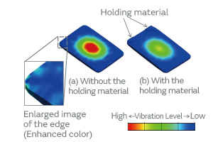
Fig. 10. Distribution Diagram of Vibration
Fig. 11. Relationship between Blank Width and ESR
(4) How to Find Optimum Solutions
The parametrization of the blank length and the blank width at the same time using Femtet has enabled us to present the relationship between the blank geometry and the ESR characteristics in a matrix form as shown in Fig. 12. This approach has enabled us to compute the optimum geometric parameters as a sized area, which past models were able to compute only as a point.
The improvement of the above-mentioned four points has enabled us to achieve a higher degree of consistency of simulation characteristics with the actual sample characteristics, allowing us to find the optimum geometric parameters as a design area. The center of this design area will have highly stable design values that will be able to maintain good characteristics even if the corresponding geometry is not stable. Among the design values A, B, and C of Fig. 12, the design value A in the center is stable over the variation of temperature compared with the temperature characteristics of the actual samples (Fig. 13) and exhibits the ESR satisfying the target value, whereas the design value C exhibits high ESR, which is not suitable as the model. The design value B at the boundary of the area is problematic as the ESR of the actual sample has a tendency to increase in the higher temperature region. The design value B did not exhibit its problematic nature in the small-scale prototype production; however, as the number of prototypes increased, the number of characteristic defects increased because of variance and so forth, which forced us to redesign the product in some cases. However, the method using Femtet has finally allowed us to efficiently conduct design work that has excellent robustness against geometric parameters.
Fig. 12. ESR Analysis Showing the Optimum Design Area
Fig. 13. ESR Temperature Characteristics
5. Conclusion
We consider this simulation method using Femtet highly consistent with the actual sample characteristics, which we believe would help improve the quality of device design work. By efficiently improving the product design process, we strive for the reduction of lead-time of sample preparation for customers’ requests and preparation time for volume supply as well as for providing more stable quality products.
Glossary
*1 Finite Element Method:
Abbreviated as FEM. A technique of numerical analysis for finding approximate solutions to a whole structure by dividing the structure into a collection of smaller domains for computation.
*2 ESR:
Equivalent series resistance. A resistance primarily due to losses inside a crystal or in a holding material.
*3 Oscillation margin:
It indicates the margin that exists from the state of oscillation to the moment when the oscillation ceases. It is one of the most important items in the oscillator circuit where quartz crystals are used.
*4 Femtet:
An analytic software system using the finite element method developed and marketed by Murata. It covers a broad field of analysis, ranging from electromagnetic analysis of electric fields, magnetic fields, and electromagnetic waves, and mechanical analysis of thermal conductivity and stress, to piezoelectric analysis and sound wave analysis.
*5 Robustness:
The quality of being strong (robust) in design, that is, the design has room for coping with various external factors, such as the variance of size.