Research and Development on Co-fired Monolithic Thermoelectric Conversion Elements
Takanori Nakamura
Original paper and venue: Lecture given at 2014 Richard M. Fulrath Award Session for the Fulrath Okazaki Memorial Association
Thermoelectric conversion technology is capable of directly converting thermal energy into electrical energy, enabling the heat sources around us to be used to obtain electricity. This technology allows the thermal energy discharged from automobiles and factories to be used to generate electricity, and so it is drawing wide attention as a new stand-alone power source. Thermoelectric conversion technology uses the physical phenomenon discovered by Thomas Seebeck in 1821, and so it has a long history. However, the thermoelectric conversion modules currently available on the market include rare metals in the thermoelectric conversion materials, resulting in high costs and limiting the spread of their application. In this study, we used ceramics, which are used as materials in Murata’s key products, as the main material, and we applied monolithic technology and co-firing technology, where our company has developed extensive expertise through the manufacturing of monolithic electronic components, to enable us to successfully develop monolithic thermoelectric conversion elements with more compact designs and higher power generation efficiency than anything developed before.
Overview of Monolithic Thermoelectric Conversion Elements
The monolithic thermoelectric conversion elements that we developed in this study were made by forming thermoelectric materials into thin sheets as shown in Figs. 1 and 2, and then these sheets were joined together directly without using electrodes. Also, insulating material was used as the insulator between the thermoelectric materials, and this was fired as a single body for providing a structure where the spatial loss was minimized. This structure enabled us to obtain the following advantages.
- Eliminated the need for boards with arranged patterns of thermoelectric elements
- Eliminated the need for connecting electrodes between thermoelectric elements
- Eliminated the need for spaces for ensuring insulation between elements
- High surface efficiency even when the number of elements is increased and can be easily developed into a compact design
- High voltages are easily obtainable even for small temperature differences
The current and voltage characteristics of the elements can be controlled by adjusting the number of stacked layers of thermoelectric materials and their thickness for easily obtaining the optimum output for a wide range of temperature environments. Furthermore, these types of structural characteristics can be utilized to enable handling as a single power generation component in contrast to previous types of usage. This allows a higher degree of freedom in installation locations and enables obtaining of the desired power generation characteristics by connecting in series-parallel combinations. On the other hand, some disadvantages are that (1) the materials that can be used are limited because the monolithic thermoelectric conversion elements are fabricated by co-firing of thermoelectric materials and insulator materials, and (2) the fabrication of large-size modules is difficult because the thermoelectric materials are stacked in sheets for building modules, and so this structure is not suited for large-scale power generation in the kW range.
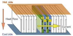
Fig. 1. Configuration of Monolithic Thermoelectric Conversion Elements
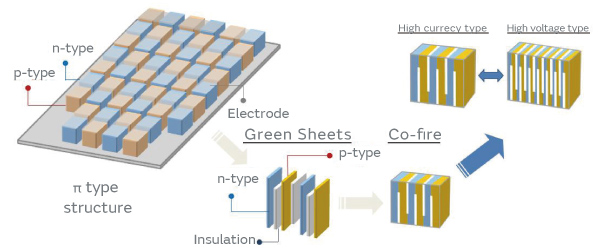
Fig. 2. Fabrication Method for Monolithic Thermoelectric Conversion Elements
Characteristics of Thermoelectric Conversion Materials and Monolithic Thermoelectric Conversion Elements
The monolithic thermoelectric conversion elements that were fabricated in this study used La-doped SrTiO3 as the n-type material, Mo-additive Ni as the p-type material, and partially-stabilized zirconia as the insulator material. For the thermoelectric characteristics at room temperature, the n-type material and p-type material used in this study exhibited Seebeck coefficients of -153 μV/K and +20 μV/K, electrical resistivities of 1.8 × 10⁻⁵ Ωm and 1.3 × 10⁻⁶ Ωm, and thermal conductivities of 5.2 W/mK and 6.6 W/mK, respectively. As shown in the thermal shrinkage behavior of these materials in Fig. 3, these materials were adjusted so that shrinkage started from around 1200°C for enabling co-firing without applying pressure.
Fig. 3. Thermal Contraction Characteristics of Component Materials of Monolithic Thermoelectric Conversion Elements
The overall appearance and internal structure of the element after co-firing are shown in Fig. 4. The size of the monolithic thermoelectric conversion element produced as a prototype was 6.0 × 7.0 × 2.7 mm, and the internal structure consisted of 50 pairs of a 25-μm thickness p-type layer and 100-μm thickness n-type layer joined together with a 5 μm insulator layer sandwiched between them. The power generation characteristics of the fabricated element are shown in Fig. 5. The electromotive force under no-load at a temperature difference of 10°C was 50 mV, the maximum output was 100 μW, and the voltage and current characteristics at maximum output were 25 mV and 4 mA, respectively. When a further temperature difference of 40°C was applied, the electromotive force under no-load was 170 mV, the maximum output was 1.2 mW, and the voltage and current characteristics at maximum output were 80 mV and 15 mA, respectively. When the output characteristics were measured at high temperatures for evaluating the thermal resistance, power could still be generated in environments at a temperature difference of 360°C (high-temperature section: 380°C, low-temperature section: 20°C), and the maximum output was 0.19 W. Converting this output value to output density per unit area gives us 0.45 W/cm2.
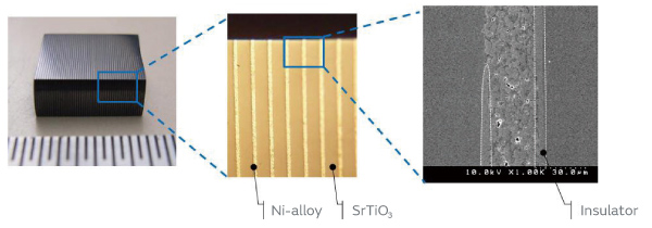
Fig. 4. Appearance and Internal Structure of Multilayer Thermoelectric Conversion Element
Fig. 5. Power Generation Characteristics of Multilayer Thermoelectric Conversion Element (Left: Temperature Difference of 10°C, Right: Temperature Difference of 40°C)
Application to Wireless Sensor Network Power Supply
Recently, there have been growing expectations for the spread of IoT (Internet of Things), which enables sensing of a wide array of devices, infrastructure, and biological states and other data and connects and uses this information over the Internet. Sensor network terminals are essential for realizing IoT, and researchers are striving to develop terminals with more compact designs and greater functionality. At the bare minimum, the required components for a sensor network terminal are a power supply unit, power control IC, capacitor, sensor, control IC, and wireless device. Normally, power is supplied in the power supply unit by a battery or cable, but if thermoelectric power generation can be used to obtain electricity from the heat in the measurement environment, a terminal can be developed that continues to operate as long as a heat source is available. In this study, a prototype of a sensor network terminal was built incorporating a temperature sensor and wireless module and using the monolithic thermoelectric conversion element as the power supply, and then operation was verified. The terminal built as a prototype in this study is shown in Fig. 6. In environments with a small temperature difference like those simulated in this study, the output voltage of the thermoelectric conversion element is in the range of a few tens of mV, and so a voltage step-up DC-DC converter and capacitor are required for operating the control IC and wireless device. The minimum operating voltage of the DC-DC converter used in this study was 25 mV at 4 mA, and so if the prototype monolithic thermoelectric conversion element is used, it can operate semi-permanently in an environment with a temperature difference of 10°C or more.
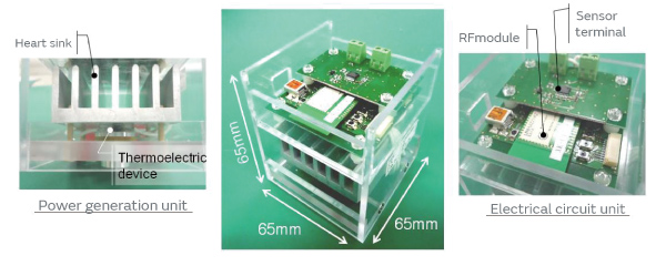
Fig. 6. Prototype of Sensor Network Terminal Incorporating Monolithic Thermoelectric Conversion Element
The installed sensor was a thermistor-type temperature sensor, and a sub-GHz band module was selected for the wireless device. This prototype terminal does not have any primary batteries or switches, and once an environment at the predetermined temperature difference is obtained, it automatically starts operation and performs wireless transmission of temperature readings and measurement information. This wirelessly-transmitted information is received by a receiver connected to the USB port of a computer, and display software can be used to confirm the ID of the transmitting terminal together with the transmission time and measurement temperature information. To verify the operation of this prototype sensor network terminal, operation intervals were measured using a heater warmed to 60°C and an air-conditioned environment at 25°C. The power supply was found to have the terminal register temperatures and send the measurements at intervals of approximately 15 seconds. Next, the prototype was installed on a heat duct for conducting a test in an actual usage environment. A photo of the installation setup is shown in Fig. 7. The gas temperature inside the duct, on which the terminal was installed, was 120°C, and the temperature of the outer wall of the duct was around 70°C. The outside air temperature which serves as the cooling source varies depending on the season, and so this also affects the temperature difference, but even in the summer months when the outside temperature was high, operation was stable, and we confirmed that it operated without requiring any maintenance over the course of one year.
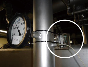
Fig. 7. Demonstration Test for Sensor Network Terminal
Conclusion
In this study, we successfully developed a monolithic thermoelectric conversion element that can be used in sensor network terminals. Compared to conventional π-type modules, the monolithic thermoelectric conversion elements have unique structural features that led us to propose a new type of thermoelectric element. We built a sensor network terminal incorporating the prototype thermoelectric element and verified its operation. As a result, we were able to demonstrate that operation was possible in an environment with a temperature difference of 10°C or more, indicating its feasibility for practical application. However, there are still many points that can be improved, and the output characteristics of the module must be improved in the future to enable operation for narrower temperature differences, shorter operation intervals, driving of multiple sensors, and other operations under additional loads. And so, many issues still remain, including enhanced weather resistance and incorporation of heat sinks for enabling long-term stable operation. From here, we will work to improve the materials and optimize processes for resolving these issues and to enable development of a marketable product as soon as possible.